DIY Mesh Node
✳︎
Rooftop Solar Repeater
✳︎
DIY Mesh Node ✳︎ Rooftop Solar Repeater ✳︎
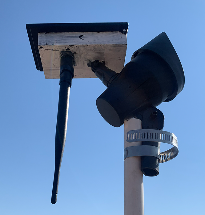
DIY Rooftop Solar Mesh Repeater
I had some serious technical hurdles and didn’t get fantastic documentation of my step-by-step process, but I wanted to share this with you good folks in case it inspires your own projects
I started this project by trying to follow a rather difficult-to-follow tutorial I saw on a YouTube reel. I thought it had fairly comprehensive instructions, but once I’d ordered the listed hardware and began assembly, I realised that this person may not be as knowledgeable as I had previously hoped. I hope that this guide will be at least slightly more useful for you good Meshtastic and MeshCore enthusiasts.
After speaking with the legendary owner of www.nmmdc.org, I realised I would need to get an entirely new parts list. They are listed here:
Internal Hardware
Harbor Freight Solar Power Spotlight - $8.99
RAK4631 Mesh Node Module - $19.97
3.7V Rechargeable LiPo Flat Pouch Battery with 2.0mm 2-pin connector $6-12, I got mine as part of a multi-pack a while back and had to rewire it to match the board’s polarity
JST ZHR-2 1.5mm Pitch Male Pin Cable - $0.75, I had one leftover from a Heltec V3 node. ALWAYS CHECK YOUR POLARITIES WHEN CONNECTING POWER TO YOUR BOARDS!
915 Mhz SMA Antenna - $5-15, I got mine a while ago but the linked one should work
Additional Tools and Resources
I also used screw drivers, pliers, white paint and a paintbrush, zip ties, adjustable band/hose clamps, PVC pipe, self-bonding super tape, and electrical tape. I’m sure you can figure out how to do this with other tools as well, but I gotta mention it for the folks who care!
Steps
I flashed the Mesh node. If you’d like to make a MeshCore repeater like I did, you can follow this tutorial. Be careful to connect your antenna to the board before plugging it into the computer USB or any other power source, as it may try to send a signal and if it’s not connected to the antenna, it can fry your board!
I connected the battery to the board so it would charge with USB for an hour or so before it had to charge through the solar input. More info on how to do that safely on Step 8.
I gutted as much of the solar spotlight as I could. I unscrewed the board inside, removed the cables to the solar panel and light AFTER noting the polarity of each (if you cut them with a little of each connected to the board, you can reference how they were connected later), and used pliers to break out the remaining plastic that wasn’t in either of the two major rectangular housings. One is an exterior piece that keeps out water, and the second is what creates a nice seal to the solar panel. Keep both of them! If you’re following along, you should have even disconnected the cable connected to the light. I was initially planning to remove the light part entirely, but it actually provided a nice connector to the PVC pipe.
I painted the underside of the solar box (but not the actual solar panel) white to reflect as much of the desert sun as I could. I plan to repaint with a sturdier finish in time, but for now it’s just some glossy acryllic I had laying around.
I drilled out the power switch hole a little extra, just enough to mount my antenna through the bottom.
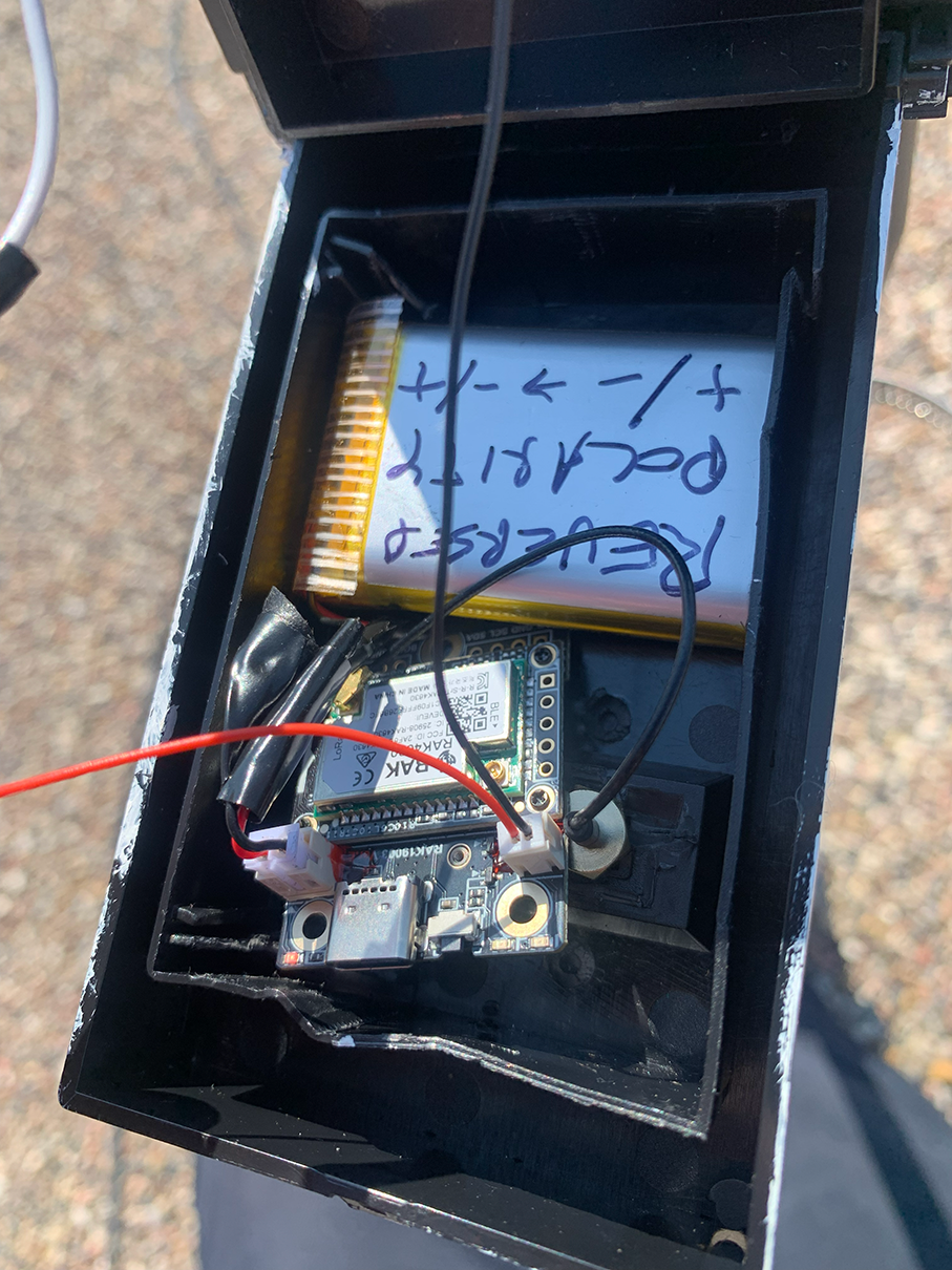
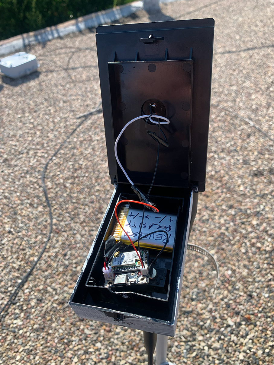
I laid out my board and battery in the solar housing so I would know exactly how I would connect them later.
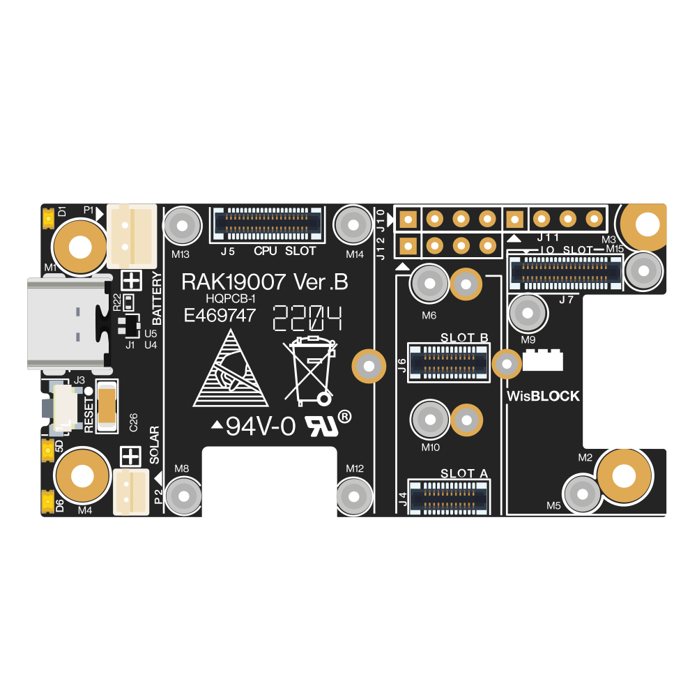
I used electrical tape and a pocket knife to scrape open the wires to the solar panel a little wider, then twisted them and the JST ZHR-2 1.5mm pitch cable ends together and electrical taped them. I did this one at a time with a piece of tape on the solar panel cables to avoid any chance of them shorting out. Because the RAK4631 is actually comprised of a RAK4630 and RAK19007 soldered together, I had to check this RAK19007 diagram from the Rokland website to confirm the polarities on the board. Be sure to save this for future use, as the polarity notation was covered up by other wires on my board!
I connected the 37.V flat pouch battery to the board. I realised that my battery actually had reversed polarities, so I cut one wire, taped the ends so they wouldn’t short, and then cut the second wire and attached it to the opposite side. After securely taping it with electrical tape, I reattached the leftover sides, so now black was connected to red and vise-versa. You may not need to do this with your battery, but be sure to check to avoid your battery exploding! I also noted the swapped polarity with a Sharpie in case I need to mess with it in the future.
I closed up the housing, making sure to keep the wires from getting caught in the plastic.
I tested the repeater to make sure there were no issues with it powering from solar and pulling a charge to the battery.
I used my self-bonding super tape to cover the gaps in the plastic on my 915 Mhz antenna so rain hopefully won’t get into it. I also used a hot glue gun on the base where the antenna connects to the solar housing to hold the antenna in place while still allowing for ventillation through the hole that once housed the on/off switch. If you do this, be sure to avoid getting too much glue onto the actual antenna, so you can remove it for repairs/readjustment in the future.
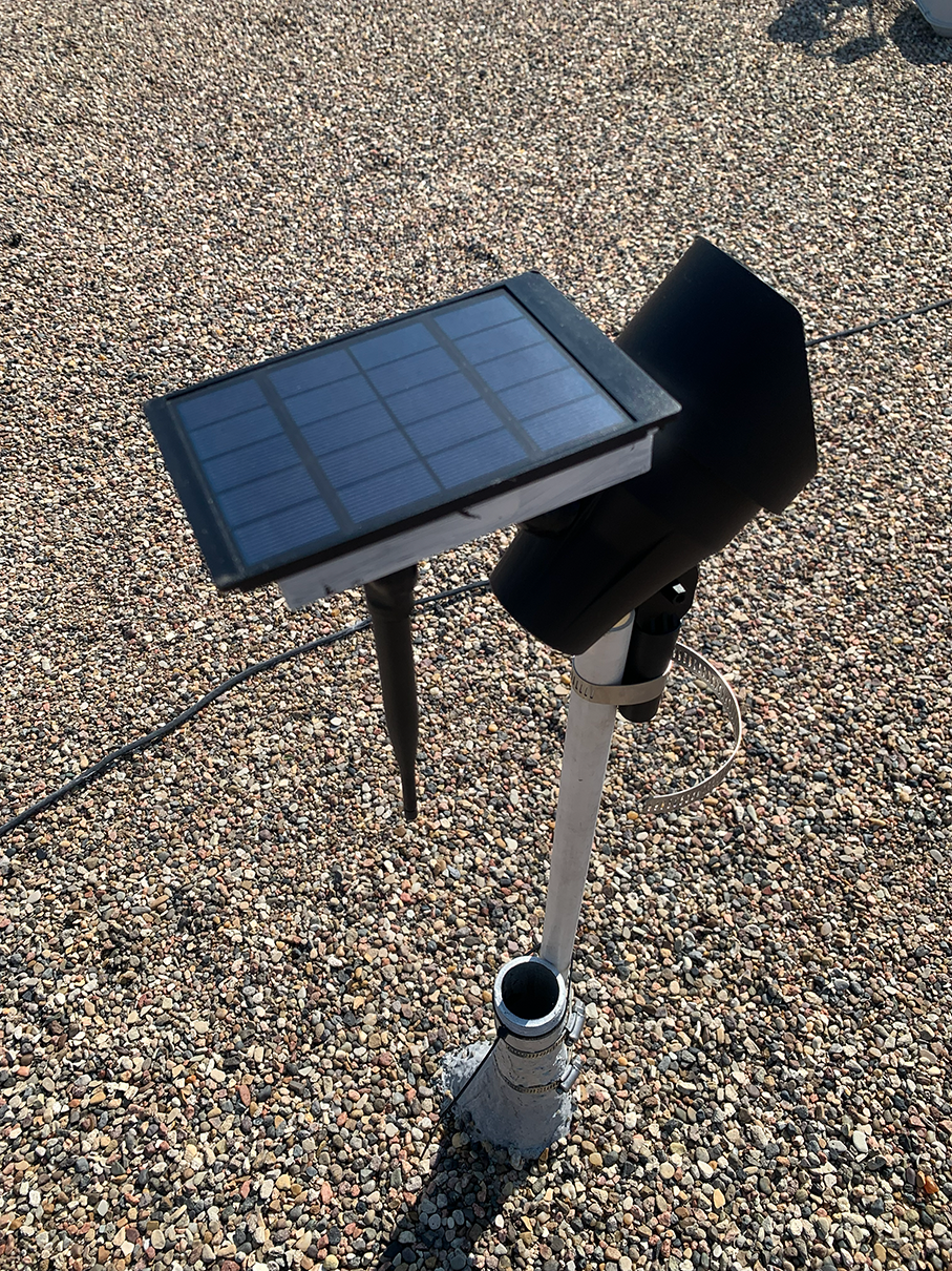
I used a hose clamp to tighten the solar panel to my PVC pipe. I accidentally over-tightened it, so be careful when you do yours to avoid it snapping or something. I considered using a metal pipe, but I thought there was a small chance it may mess with the LoRa output and I decided to play it safe with the PVC.
I went onto my roof, put the hose clamps around my PVC pipe (unclamped for the moment) ziptied the PVC pipe to an air vent pipe (without covering the hole so I can still get fresh air into my house), and then tightened the hose clamps around the air vent and PVC pipe in two spots to hopefully help in the event of a good old-fashioned New Mexico windstorm.
I tested the rooftop repeater in its new location. I won’t include the steps where I realized I’d messed up the firmware, had to unplug the solar and battery from the board before unscrewing the locked-in antenna, went back into my house, screwed in another antenna to avoid shorting the board, flashed a firmware deleter, and then re-flashed a new firmware, and then reconnected everything on my rooftop. It was a pain and I don’t want to bore you.
Success!! Rooftop repeater that was so easy and wasn’t so frustrating that I considered abanding the project numerous times at all!
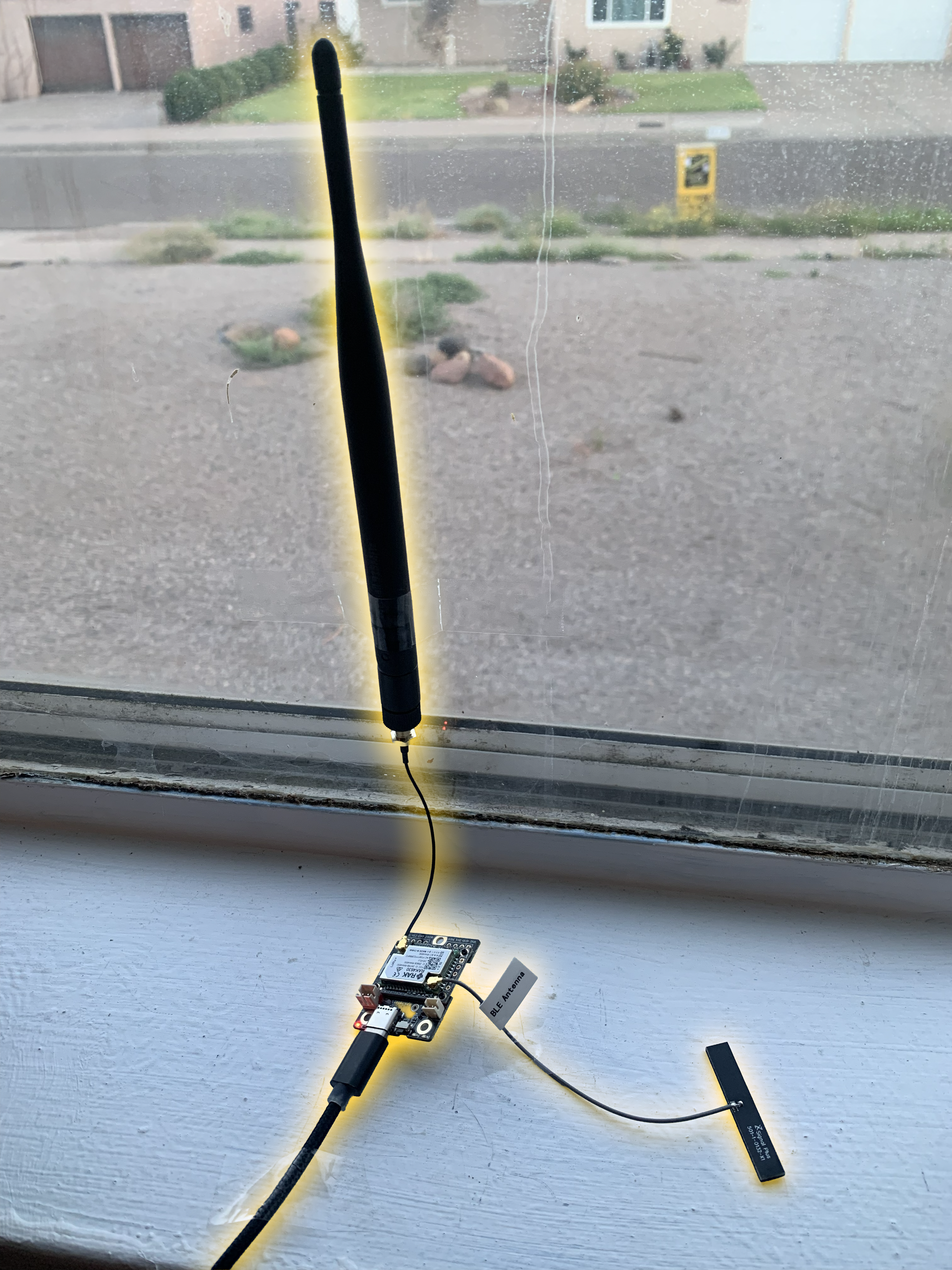
Additional Notes
I used the RAK 4361 board because it is low power and also built for solar. It is also a lot more resistent to outdoor elements than other boards, so it will hopefully be resistent to drift or giving out with too much heat or humidity (that I am trying to mitigate as best I can regardless).
I know that antennas like this are normally not upside-down, but I read that the geometry of their signal pattern shouldn’t change too much. It seems to be working okay on my roof, so that’s where we are.
This build is definitely not stress-tested. I’m sure something will break. Hopefully the plastic is strong enough to keep the whole thing from flying off my roof. I am assuming that the solar housing will be strong enough to keep rain out of the boards, but the modifications I’ve made may still cause drainage issues for condensation/humidity. I’m hoping that the drainage holes in the box will be enough, but I guess we’ll find out.
I am aware how janky it is to use an unusable light as essentially an arm for the solar panel. I don’t care, as it’s on a flat roof that won’t be seen by too many folks. You can probably figure out how to do this much better, and I hope you contact our collective (Tell ‘em to forward it to Scotty) to brag about how much better yours is. Just send me your build notes so I can rip you off ;)